 |
| |
SMALL
LAYOUTS &
SHUNTING
LAYOUTS
THEIR
HISTORY, CONCEPTS & OPERATION
|
| |
| The
status and the perception of small layouts as well as of
dedicated shunting layouts has changed significantly
within the railway modelling community over the past few
decades. Once a modelling niche they have become a layout
type bordering on mainstream. Here's a brief overview of
how and why this happened, the advantages of small
layouts, and how they relate to shunting layouts. |
| |
| |
SMALL
LAYOUTS
How small is "small" ?
|
| |
| Describing
any object as small is, of course, not a very accurate
label as it requires a point of reference: small in
comparison or relation to what? In addition, we all know
that certain objects can change their dimensional
qualities. |
| |
Source: Model
Railroader
|
|
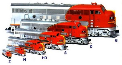
When
compared to its G scale counterpart, an HO scale
locomotive will appear to be quite small, but
that very same engine will appear big when we
view it alongside a Z scale model. The notion of size in model railways
changed as smaller scales were introduced over
time: HO (1:87) in the early 1920s, TT
(1:120/1:130) in 1945, N (1:148/1:160) in 1962,
and Z (1:220) in 1972.
A similar change - although only partly
linked to the introduction of smaller modelling
scales - has occured in the perception of just
how small a "small layout" can be for
it to be worthwhile to build and run trains on.
|
|
| |
| From a historical
point of view, the implicit message of the increasingly
popular (and therefore influential) model railways hobby
press was to "think big" and to be inspired by
modelling giants such as John Allen (whose Gorre &
Daphetid layout filled an entire basement from floor to
ceiling in his California home) or the Pendon Museum
layout (which fills the entire sprawling ground floor of
a building in Oxfordshire). In his 1978 Creative Model
Railroad Design, John Armstrong concluded that,
based on a Model Railroader survey, model
railroaders were indeed "denizens of the
basement" as that was precisely where 51% had their
layouts. 20% were located in a spare room, 7% in a
garage, 4% in the attic, and another 4% had a
purpose-built added room. In other words: at least 86% of
the participating modellers in the late 1970s indicated
having a spacious setting at their disposal - and thus
felt no constraint to not go for a "basement
empire".
|
| |
| This was
not, however, the case with British and European
modellers, who have seemingly always been plagued
more by a lack of space than their American
colleagues - and the more restricted options
available to them ultimately created the
archetypal British "branchline terminus to
fiddleyard" layout. In terms of track design, the
fiddle yard is a simple staging area
with a number of tracks which allows the
rearranging of trains off the layout proper. It's
true importance, however, lies in its conceptual
design:
"The basic
idea is simple. You just end the layout in a
few parallel sidings, and carry out any
necessary rearrangement by hand. These
sidings represent the rest of British
Railways." (Freezer, 1961)
The fiddle yard started to appear in the late
1930's when British modellers wanted to operate
small layouts in a realistic manner; in the
1950's, Cyril J. Freezer would regularly feature
fiddle yard to terminus type layouts as editor of
Railway Modeller and as such had an enormous
influence in spreading the concept and making it
popular - adding his own design,
"Minories", to the classic track plans
of that layout type.
|
|
 |
|
| |
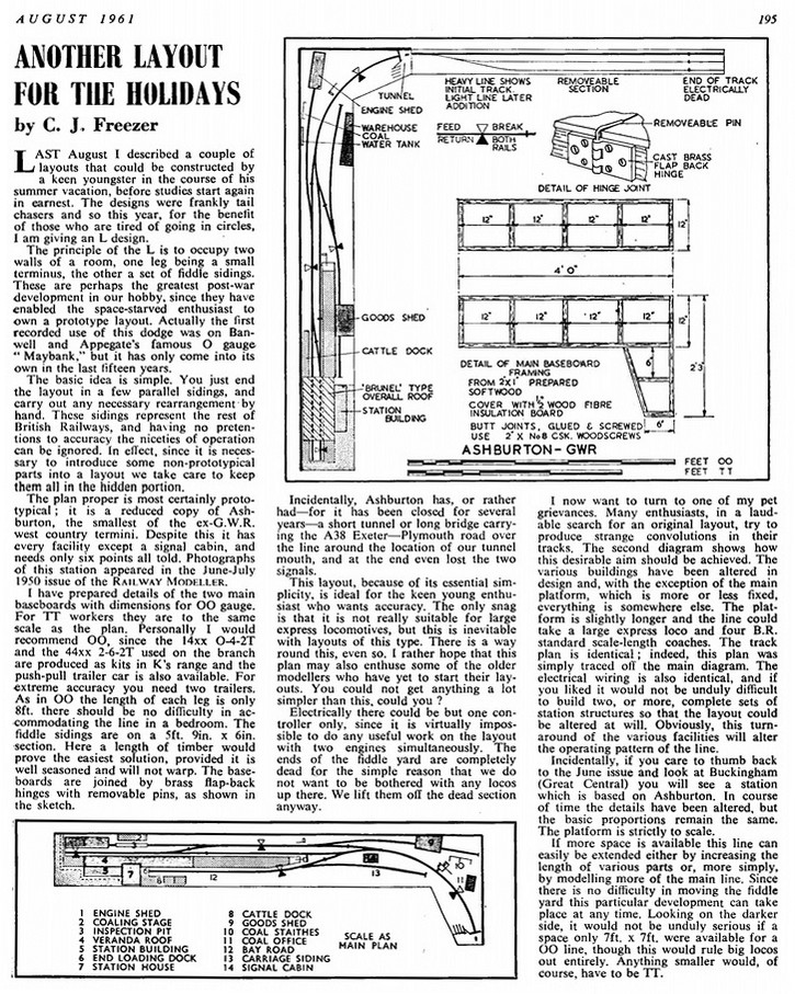
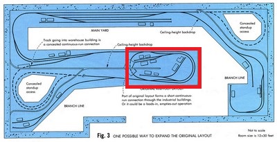
The example shown here is from the August 1961 issue,
in which Freezer pointed to another feature often
associated with terminus to fiddleyard layouts: the L
shape.
"The principle of the
L is to occupy two walls of a room, one leg being a
small terminus, the other a set of fiddle sidings.
These are perhaps the greatest post-war development
in our hobby, since they have enabled the
space-starved enthusiast to own a prototype
layout." (Freezer, 1961)
It became nothing less than a
blueprint for legions of British layouts and is still
widely featured today simply because it is a proven
concept. Also used in European modelling, though often
for the purpose of switching trains "behind the
scenes" on a continuous run layout, it is known to
German modellers as Schattenbahnhof, literally
meaning "a shadow station", i.e. not intended
to be visible to any onlookers.
Freezer was a good friend of Linn
H. Westcott, whose track plan designs were as influential
in the US as Freezer's were in the UK. However, this
didn't stop the concept of what would be called a
"small" layout going off in completely separate
directions in the UK and the States. While UK modellers were busily building what
would come to be called "shelf layouts" with
fiddle yards, a small layout to their American cousins
was more like a solid plank measuring 4'x8' (120 x 240
cm).
|
| |
 |
|
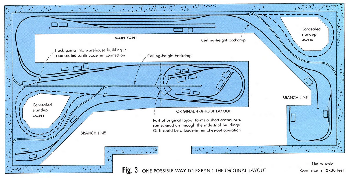
When Model Railroader
published a collection of track plans in 1981
from past issues of the 1960's and 1970's,
prolific track plan designer Ed Vondrak presented
"a small track plan designed for
growth": a solid 4'x8' (or preferably
even 5'x9') continuous run which could be
incorporated into a larger pike later on - and
the accompanying design once again pointed model
railroad planers to the basement or a spare room. One or two truly small
layouts are present in the publication, but they
were labelled "portable layouts". And
again, it ultimately all pointed to a much larger
setting.
|
|
| |
"Portable layouts
offer the chance to model railroad with a minimum
outlay of space, expense, and time. They allow us to
practice the fundamental concepts of layout design
which we will need to understand when the time comes
to build that larger, permanent layout."
(E.S. Seeley Jr., in Hayden 1981)
|
| |
| Driven by an entirely
different perspective and mindset, British
railway modellers continued to develop the
concept of the "terminus to fiddle
yard" further, effectively shrinking it from
running around two walls of a room to a short
linear layout - and the resulting "shelf
layout" formula gradually became an accepted
mainstream practice for those who wanted a layout
but lacked the space and/or the inclination to
build a fully blown mainline setup. The prototype
settings modelled continued to be mostly
backwater branchline terminus stations, but the
approaching line of track got shorter and
shorter. |
|
| |
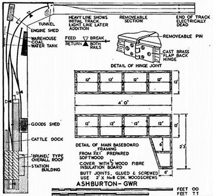
| A
very compact (4'-6" x 13" / 135 x 32,5
cm) example of this type of British shelf layout
is Dennis Beale's "Raikes Street" (an
article on this layout appeared in the January
1995 issue of Railway Modeller), which
differs from other shelf layout settings by
featuring a moveable piece of track concealed
within a factory building which drastically cuts
down on the speace needed for its runaround track
arrangement. |
|
 |
|
| |
| In contrast to this, back in
December 1992, Model
Railroader featured a project layout built to the
"classic US" 4'x8' oval continuous-run formula
and labelled it as "a small layout anyone can
build". This is not to say that short
and narrow layouts were unheard of in US modelling - but
they were the exception to the rule and generally few and
far between. |
| |
| |
Small layouts: (almost)
mainstream modelling
|
| |
| But things were slowly changing -
the popularization of the internet since the
mid-1990s gave new railway modelling ideas a
massive boost as the world wide web profoundly
changed the way the hobby communicates and
conducts research. The popular hobby
magazines on both sides of the Atlantic were
still showcasing big and beautiful layouts, but
the railway modellers who first took to the
internet were less so inclined. Very often, the
layouts they were building, operating and
describing on the web were small shelf-layouts,
some of them even in "minimum space".
One important
such example which became a source of inspiration
for many was Scot Osterweil's NYC Highland Terminal
switching layout, which made its online debut in 1994
(Scot presented an update in Kalmbach's 2015 How to Build Small Model
Railroads).
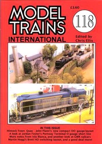
But it was not all virtual
- in the UK, Chris Ellis, former editor of the Airfix
Magazine, produced and published Model
Trains International, highlighting a
modelling approach which was the pure anti-thesis
of the sprawling British "Railway of the
Month" and the US "Basement
Empire" and focused on shortlines pretty
much around the globe (MTI, which had a
small but loyal readership, ran for a total of
118 issues before being cancelled in 2015 as
Ellis retired).
Gradually, the concept of building and
running a small layout in its own right and not
as a stepping stone or a stop gap on the way to
the XXL size "dream layout" had
progressed into UK (and, to a lesser extent,
European) mainstream modelling.
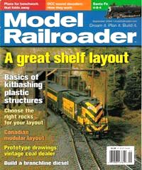
It also
started to appear more and more in North American
modelling, as the cover of the September 2004
issue of Model Railroader shows.
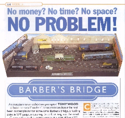
Even smaller layouts
started to appear in the UK, which were just one
little step up from a static diorama - such as
Tony Wood's Barber's Bridge (which was
featured in the January 2000 issue of Rail Express
Magazine).
An absolute minimum-space layout, the scenic section of this diesel
fuelling point measures only 22" x 8"
(55 x 20 cm), with an additional 14" (35 cm)
of hidden track allowing for movement of the
locos onto the three short sidings. The layout
was built within a few weeks and at a cost of
just £20 at the time.
|
|
|
|
| |
Over the years, various concepts evolved
around what came to be called "minimum space
layouts" in British modelling terminology.
Most of these center on how to run trains on a
small layout in order to sustain interest in it,
but some have taken up the question of how small
a layout can get and still be workable, leading
to a whole range of "micro layouts"
which really are as small as you can probably
get.
This modelling concept
found its master in the late Carl Arendt, whose
excellent website on micro layouts is still being run and
updated to this day: the micro and the
minimal space layouts really form a special
category of small layouts (which often also allow
the use of larger modelling scales in spite of
the small overall layout footprint, such as e.g. Jim Read's O Gauge 7mm
micro layouts).
Carl Arendt's
early internet presence (he launched his website
in 2001) along with his books no doubt helped to
make the concept more popular with North American
modellers.
|
|
 |
|
| |
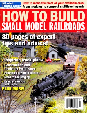
| Just to which extent the
popularity of small layouts has grown in the US can be
seen from the fact that Model Railroader issued
a special edition on how to build and run small layouts
in January 2015. |
| |
 |
|
The
layouts portrayed include a wide variety of
structural concepts (including a modular
approach) but they also illustrate that the
understanding of what can rightfully be called small
is still open to interpretation as room sized
pikes find their place as well (where possibly
the characterization narrow would be
more appropriate as they tend to run along the
walls of a room). Also included is a portrayal of
John Allen, who way back in the 1950s already
felt that modellers should
"start
small and build well. Plan your small
railroad for operation rather than as a race
track, and build it with care. You will be
amazed at how much fun a small pike can
be."
How
much the "small layout" has shrunk over
time can be glanced from the fact that his
original Gorre & Daphetid RR - to which Allen
was refering in the quote above - had a footprint
of 3'-7" x 6'-8".
Newer layouts depicted
in How to Build Small Model Railroads,
however, show a clear tendency of leaning more
and more to the (smaller) British / European
shelf layout concept.
A follow-up publication
in 2018 titled Build a Small Railroad
offered a similar collection of smaller and
not-so-small layout concepts.
|
|
| |
| |
Small layouts:
real world inspiration
|
|
| |
| Small layouts may be the
modeller's solution to fitting a layout into a restricted
amount of space, but cramped locations served by trains
are an aspect of the real world. |
| |
| Some of the
plentiful examples to be found in urban and
suburban areas, where man-made obstacles such as
buildings and streets provide quite the challenge
of how to fit in tracks and trains, still survive
today. But the resulting complications (often
involving numerous shunting moves and awkward
loco movements) are the reason why many such
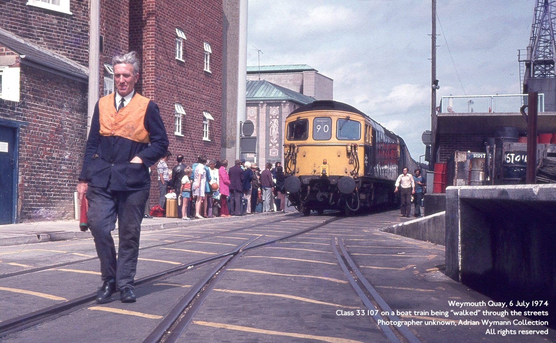
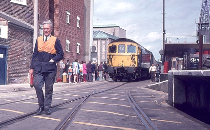
locations are no longer rail-served today. But back in July 1974,
passenger trains were still running through the
cramped streets of Weymouth on their way to and
from British Railways Southern Region's harbour
terminal, connecting with ferry services. Things
were so cramped that, for safety reasons, trains
had to be "walked" by railway staff -
who were also in charge of clearing the route of
people and badly parked cars. On occasions trains
were even escorted by British Transport Police.
|
|
 |
|
| |
| Originally built in 1865 (most
certainly in less constricted quarters), regular boat
train services ended in 1987. Special train running
continued until May 1999, and after two decades of
mothballing the line was dismantled in 2021. |
| |
 |
|
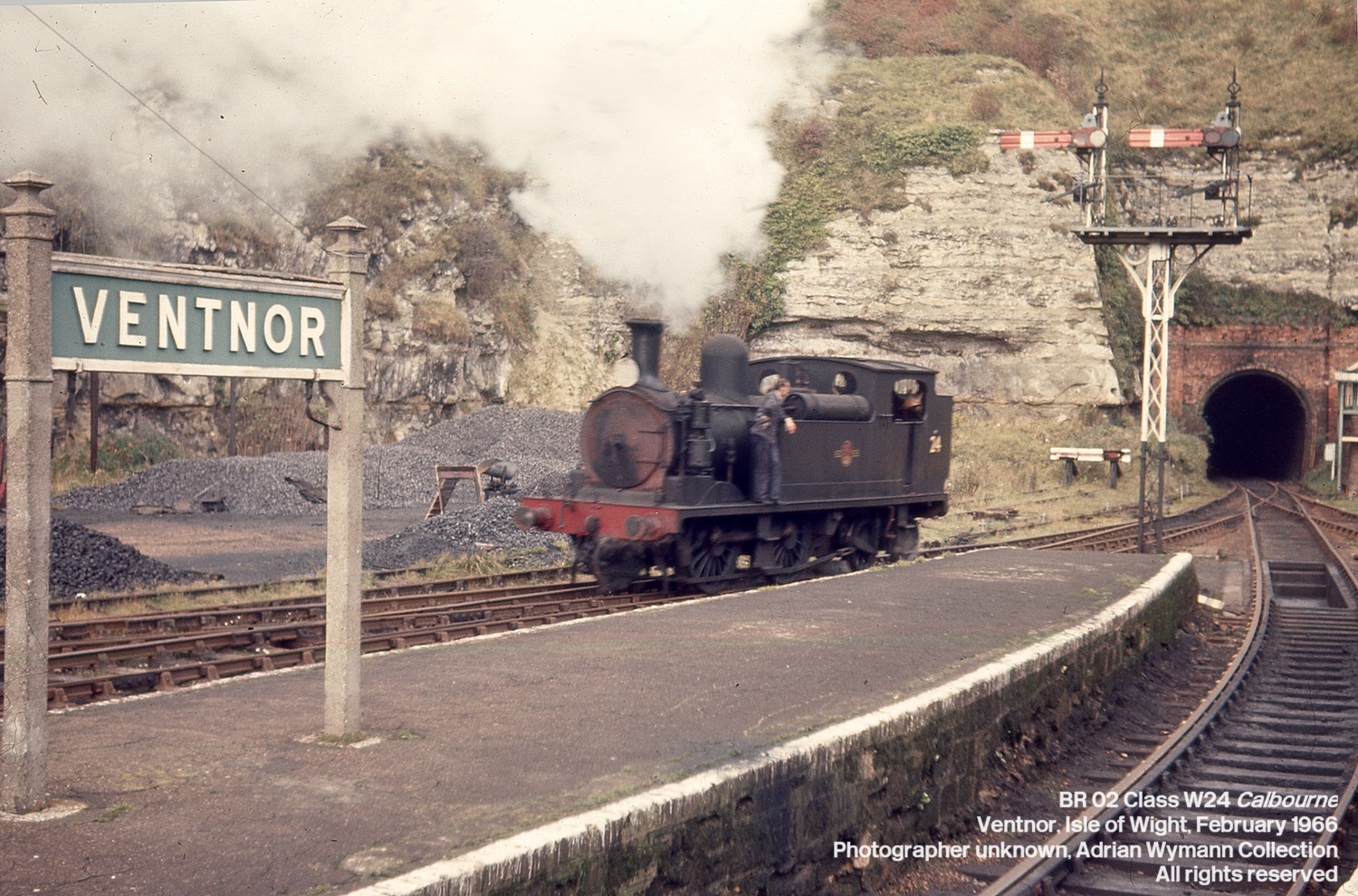
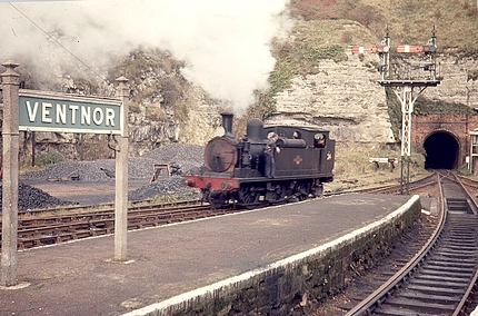
But cramped
locations were just as
plentiful in more bucolic rural locations. And
whilst these too have often lost their rail
services for the same reasons as their urban
counterparts, trains were still running to
Ventnor, the terminus station of British
Railways' Isle of Wight line from Ryde, back in
February 1966. In order to reach the station
trains had to run through a long tunnel and, when
emerging from the steep cliff of St Boniface
Down, immediately faced a three-way-point. This
had been installed to do away with the need to
use a turntable for runround moves of locomotives
- although these still had to enter the tunnel
during any such manoeuvres.
It is a scene that many
modellers would almost instantly discard as being
"unrealistic", and yet Ventnor (closed
in April 1966) was by no means a singular case.
|
|
| |
| Obviously, small layouts don't need to be based on
locations such as Ventnor, but it serves to provide
interesting cues for layout planning on how real-world
surveyors and rail companies dealt with the problem of
restricted space. |
| |
| |
Operation - the
key to sustaining interest in a small layout
|
|
| |
| On any layout - big
or small - you can either be running trains or operating
trains. "Running trains"
obviously is a broad concept. All it really indicates is
that model trains must be moving some way or another. At
one end of the spectrum, they might just be orbiting on
an oval of track at top speed, and the train might
consist of an American diesel locomotive, a couple of
Australian passenger coaches, one Swiss restaurant car
(complete with pantograph for overhead electrification),
and last but not least a British guard's van. However, in
railway modelling lingo "running trains"
usually indicates something at the other end of the
concept, namely aiming at creating a coherent picture of
both the trains and the environment they run through.
This would mean that American locomotives of a certain
period pull American rolling stock of (more or less) the
same period while running through an American landscape
of (more or less) the period in question. The amount of
compromise allowed may vary, but in general "running
trains" means that a layout will reflect some amount
of coherence and accuracy.
|
| |
| "Operating
trains" goes one step further, although it
doesn't necessarily imply a higher degree of
prototypical accuracy in terms of rolling stock
and all that goes with it. The word
"operating" is used, above all, to
indicate that models are run to reflect - but not
necessarily faithfully replicate - one very
important and central aspect of any real railway
: there's a purpose to it.
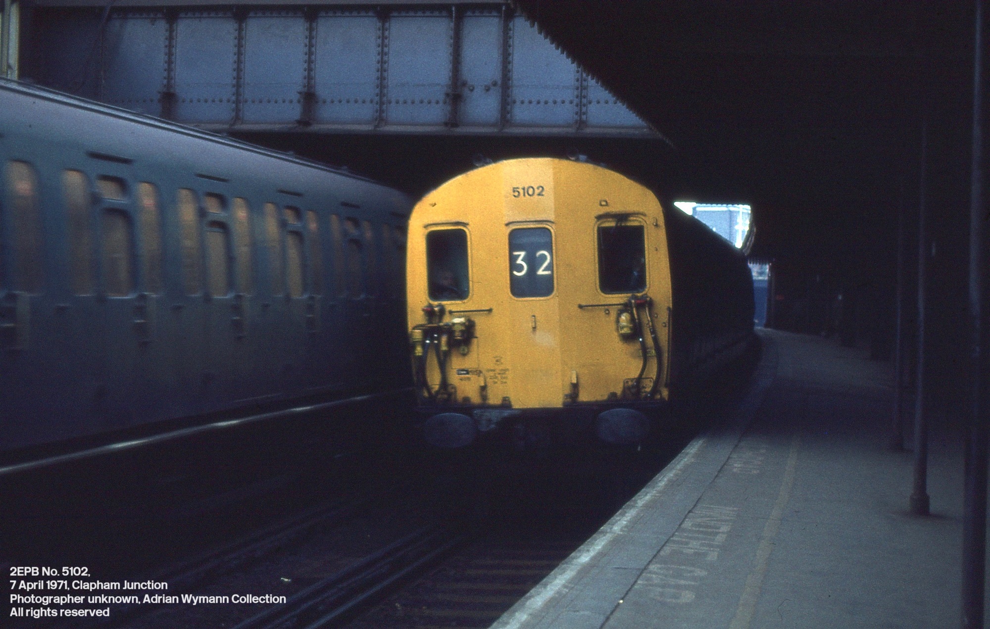
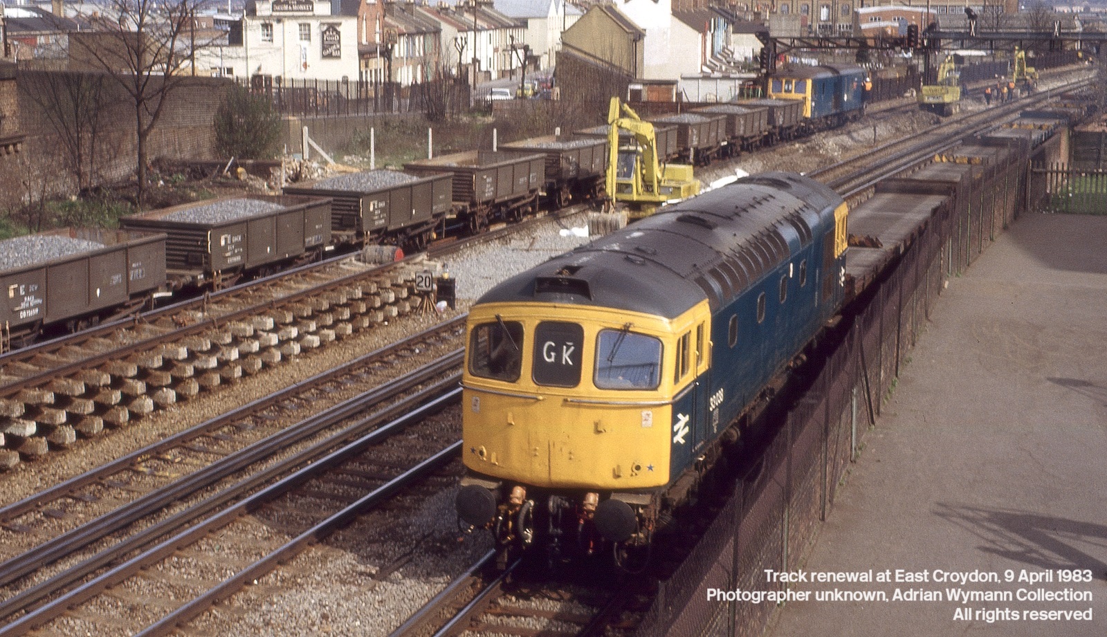
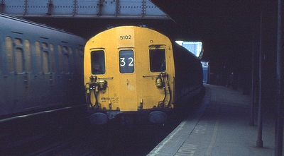
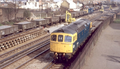
On the real railways, trains hardly ever
move "just like that". Maybe it's to
earn revenue by transporting passengers - such as
the British Rail Southern Region Electric
Multiple Unit (EMU) calling at Clapham Junction
in 1971 - or maybe it's to maintain the
infrastructure, which is the basis of being able
to run such revenue earning trains - such as the
two trains involved in extensive trackwork at
East Croydon in 1983.
These two scenes may be views from
specific areas and eras, but the same procedures
take place time and time again on rail networks
the world over.
"Operating" trains on a layout
is therefore an attempt to mimick this by
attributing a purpose to most or even all moves
taking place. Some of the concepts applied in
order to achieve this were formed in the context
of basement empires, others were developed
explicitly with small layouts in mind. Some
attempt to be as close to actual prototype
operation as possible, while others are loose
interpretations.
|
|
|
|
| |
| For
small layouts, the equation is a simple one: the lack of
space needs to be compensated by more interest generated
by the moves which take place on the layout. |
| |
Operational
concept: what a small layout is all about
|
|
| |
| Copying
the real rail transportation system's way of functioning
requires a concept. This doesn't mean that things have to
be complex or complicated - in fact, a simple concept
usually works best. A good basic way of starting is to
establish where the model railway system is located, the
era, and how it is connected to the rest of the world,
because these few points determine the traffic patterns
of a layout and thus provide
a reason for its existence - because on the real thing,
traffic pattern means customers and revenues, and without
those, railways will grind to a halt and disappear very
quickly. |
| |
 |
|
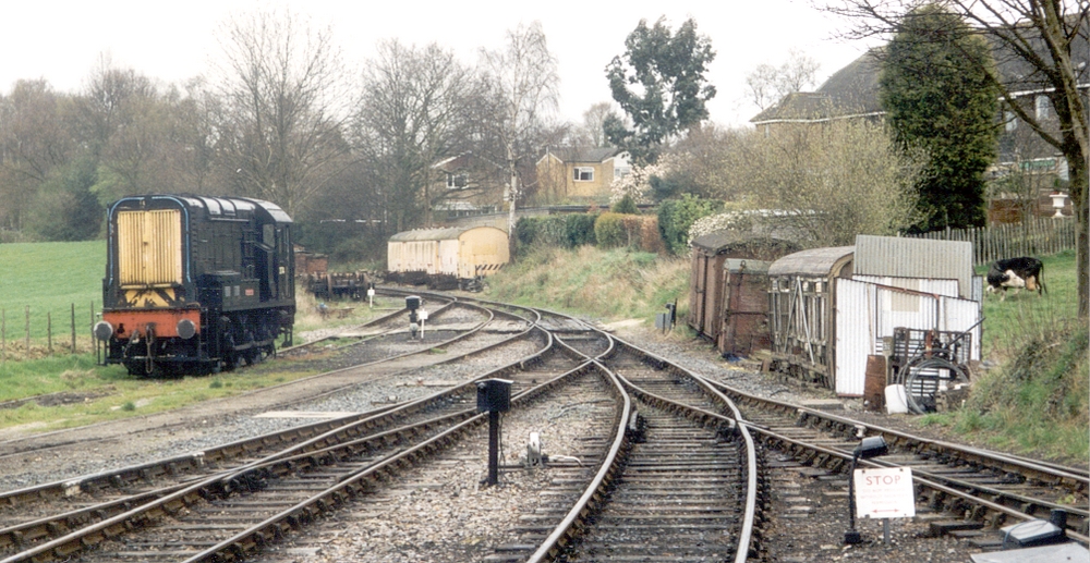
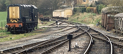
There are a
number of operational concepts which can be
applied to a small layout. You
could have mainly passenger services, or
passenger services with an equal share of
freight, or freight only, or even a specialised
setting with specialised traffic, such as a
motive power depot or a civil engineer's yard.
One possible example to illustrate this point
comes from the preserved Kent & East Sussex Railway, where an English Electric Class
08 0-6-0 diesel shunter is ready in April 2001 to
shunt stock at the railway's main station site at
Tenterden.
|
|
| |
| All of
these options are feasible, but in practice layouts which have a strong
emphasis on what can be seen as "localized
operation" (i.e. so-called "shunting" or
"switching" layouts) feature a predominance of
freight operations or are even freight-only. |
| |
| This kind of operational concept
is usually the best choice if the layout
needs to be small - simply because it
provides a "realistic feel" and
even prototypical operation within
baseboard measurements which are open to
(almost) everybody. The reasons for this are quite
simple: shunters are usually relatively
short engines, and freight stock is
usually a lot shorter than passenger
coaches.
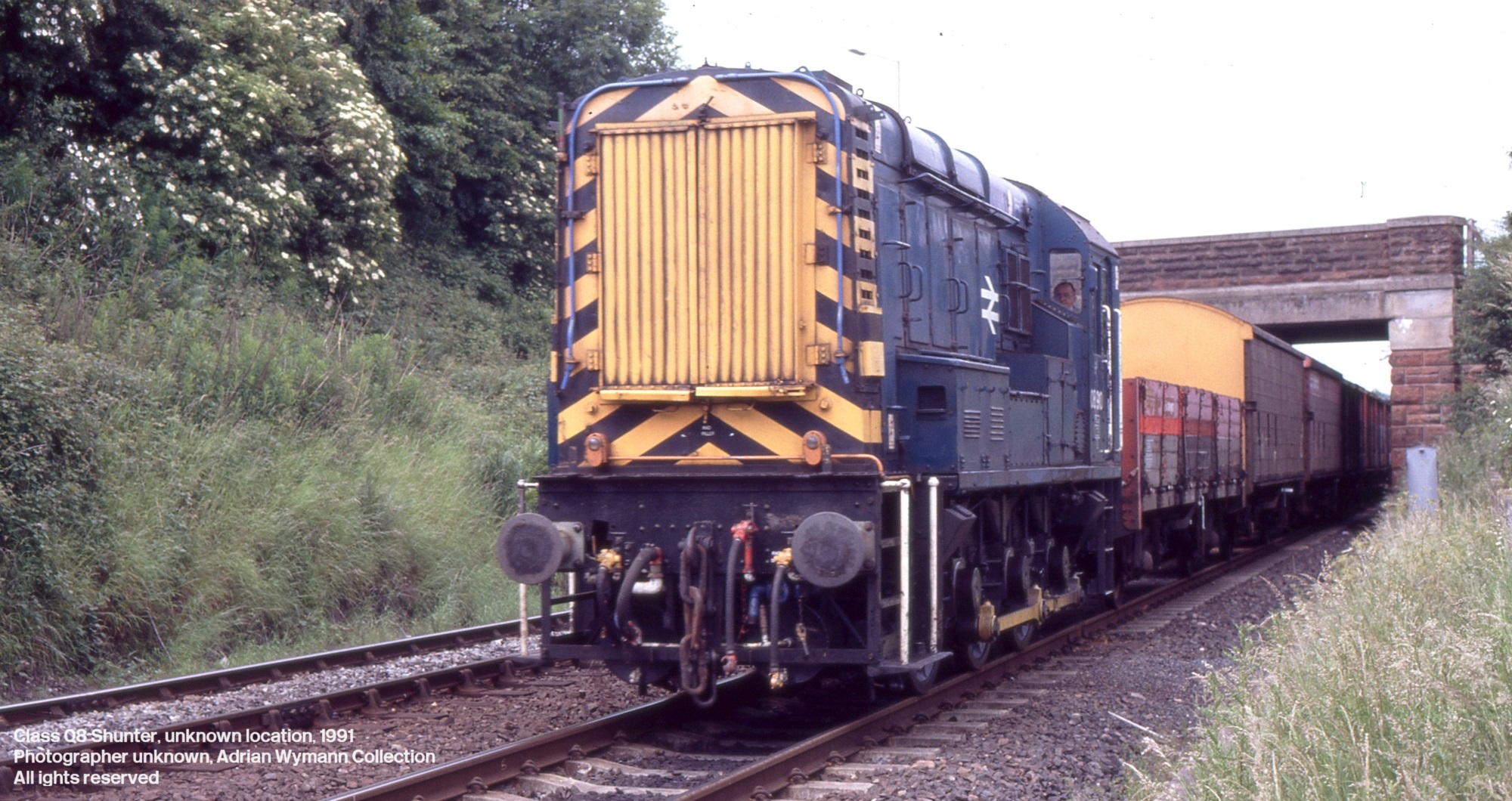
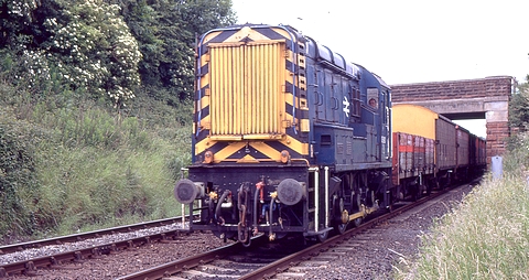
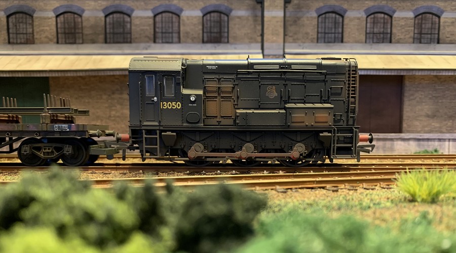
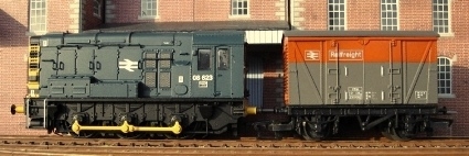
The example
shown here is a Class 08 diesel
locomotive trundling through the English
countryside with a trip working,
consisting of a short rake of assorted
waggons.
|
|
 |
|
|
| |
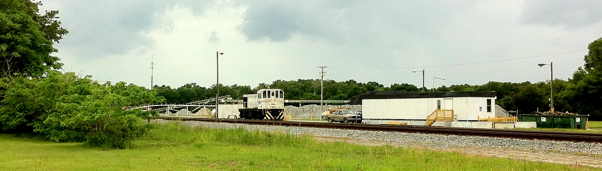
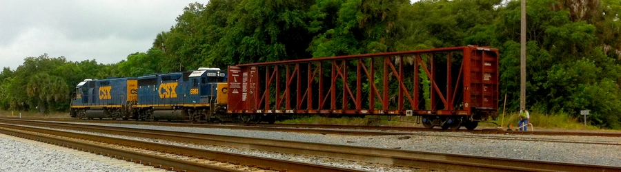
| Both Tenterden and the tracks in
a cutting, spanned by a bridge, convey the constrained
space often replicated by modellers, i.e. "cramped
quarters" with a lot of track in a small space. Certain
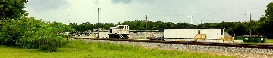
rail served industries however tend to have large
footprints and a sprawling concourse in which shunting
takes place - such as Conrad Yelvington Distributer's
aggregate terminal in Wildwood Florida, where the local
Alco S2m presents an image of a "switcher in a
landscape" in May 2014.
|
| |
 |
| |
| |
SHUNTING LAYOUTS
|
| |
| Every
country has its own approach and philosophy regarding
railway modelling, which often reflects the basic
characteristics of its own prototype railway system. |
| |
 |
|
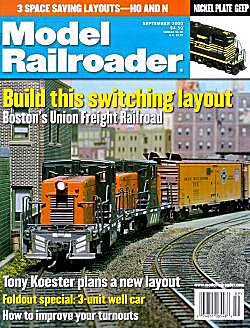
It
is therefore hardly surprising that mainstream US
railroad modelling focuses primarily on freight,
and switching layouts have been a popular facet
of North American prototype modelling for a long
time and feature frequently in magazines - such
as the Boston Union Freight Railroad, taking
center stage on the cover of the September 2000
issue of Model Railroader. Contrary to this, a
British outline model railway layout completely
devoid of any form of facilities catering for
passengers has for the longest time been unusual
to say the least. Nonetheless, the earliest
published example of a freight-only concept for a
layout seemingly comes from the UK: In the June
1926 issue of Model Railway News, A.R.
Walkley, a member of the Wimbledon Model Railway
Club (the second oldest in Britain), published an
article on his "Railway in a suitcase",
which was pioneering in terms of being H0 scale
two-rail.
The layout
also featured a system of automatic coupling
(really an essential feature for a shunting
layout) which later on was marketed by Tri-ang,
became known as the "tension lock
coupler" and is still used as standard
coupler on many UK ready to run models today (thanks
to Morgan Lee, longtime librarian of Wimbledon
MRC, for much of this information).
|
|
| |
| In
terms of British railway modelling history, Wakeley's
layout can be regarded as the ancestor of all UK shunting
layouts, as it concentrated entirely on freight . |
| |
| On a historical note, Walkley -
together with two fellow modellers from the then
newly-formed Wimbledon MRC (A. Stewart-Reidpath
and Michael Longridge) - began experimenting with
models roughly half the size of the established 0
gauge sometime in 1923. In the end, the three
modellers found 3.5mm scale to be the ideal
modelling ratio - and H0 scale was born. |
|
 |
|
| |
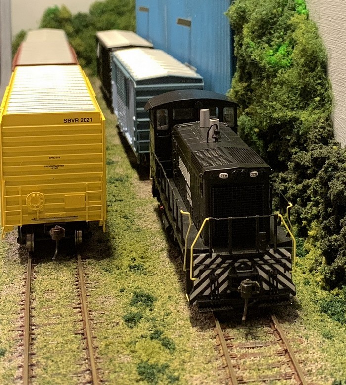
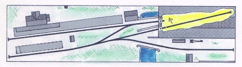
| Another
typical example of the "1' x 4' shunting
layout" type is Dave Howell's "63rd Street
Yard" - an urban yard
with a couple of freight facilities and a low-relief
backscene for added atmosphere. |
| |
Trackplan
(c) Dave Howell, used with kind permission
|
|
An American
layout as the name implies, switching moves are
taken care of by a GE 44 tonner and an S2, with
40' boxcars the staple freight stock. The 3-way
point is both a space saver and an added bonus in
creating the feel of a small and tight but
sprawling urban yard. However, shunting layouts need not
necessarily be small - they can be enormous too,
if for example they incorporate large
classificiation yards.
|
|
| |
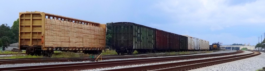
| The CSX yard in Wildwood,
Florida, would not be described as overly big by
prototype standards, yet it has a spacious and sweeping
layout and overall atmosphere which would be impossible
to model in a small space without losing much (if not
all) of its characteristics. |
| |
 |
| |
| But
even when you go for a small, shelf-type shunting layout,
it's not necessarily the lack of space which provides the
motivation for this. A number of people opt for this kind
of layout because it provides interesting operational
possibilities. |
| |
In his booklet 60 Plans for Small Locations
(first published in the late 1950s, revised in
1989), Cyril Freezer - aforementioned grand old man of
British railway modelling and layout design -
touches on the shunting layout under the title of
"special purpose layouts" and points
out that:
"It is not obligatory to
incorporate passenger facilities into a
layout, and indeed there can be very real
benefits when a small layout is designed
around a specialised service."
However, only
3 or 4 of the 60 layout plans in the booklet
reflect this statement, and to this day, the vast
majority of British modellers seem to suffer from
horror vacui in the absence of passenger
facilities on a model railway layout. More
recently, however, the internet - having gone
from a niche interest in the mid-1990s to now
being the single most important source of
information and communication platform for all
hobbies -has helped change this heavily lopsided
approach to British railway modelling.
Searching in Google for "switching
layout" yields approximately 41,800 hits
(December 2021); the string "shunting
layout" is less frequent, but around 20,900
webpages will still keep you busy perusing their
content. Plus, layouts depicting shunting yards
or switching areas are popular topics in many
online discussion groups and fora.
Operational concepts for small
shunting layouts
As their name clearly implies, small shunting
layouts already have an operational concept and a
purpose to sustain interest in running locomotives and
stock on it: shunting - which is defined
by the Oxford English Dictionary as "pushing or pulling a train
or part of a train from the main line to a siding
or from one line of rails to another"
(its equivalent in North American railway
terminology according to the US Department of
Transportation being switching).
|
|
Class 08 diesel shunter on the British prototype
layout
Little Bazeley (above)
EMD SW1500 switcher on the US prototype layout
Pecan Street (below)
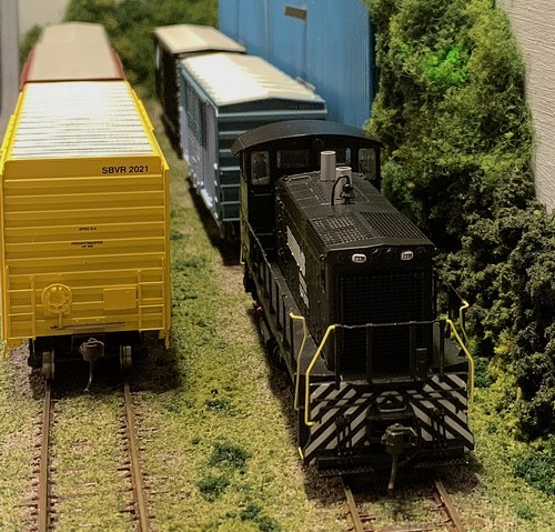
|
|
| |
| As
with any layout regardless of its size, a good basic way
to start building up a concept is to establish the
geographical setting and the era of the shunting layout
as well as how it is connected to the rest of the world.
These few points determine the
reason for its existence - in the form of its traffic
patterns, customers and revenues. |
| |
| On a small
shunting layout, there's usually only a handful
of customers receiving and generating freight. If you
take the following trackplan as an example,
things might look something like this.
|
|
 |
|
| |
| The four
customers here are represented by the first four letters
of the alphabet, but you could just as easily use the
four suits of a deck of cards, so that A = Hearts, B =
Spades, C = Diamonds, D = Clubs. A deck of cards is
shuffled and a card drawn for each freight car on the
incoming track (e.g. the lower right hand track in the
diagram above). Thus the first car in that row of
incoming traffic may draw a card of spades and be
required to be moved to industry B (= spades), car #2
hearts (industry A = hearts), etc. |
| |
 |
|
The problem with the traffic flow
generated by this system is that it doesn't take
into account the differences between customers A,
B, C and D, because rolling stock is moved to
locations regardless of its type and thus the
goods it may transport. However, if customer A is
a printer (who would above all want to receive
paper and ship printed products), he will quickly
turn his back on the railway if it keeps sending
tank cars and coal hoppers to his loading dock. |
|
| |
| A sound concept
therefore indicates the specific types of freight
received and shipped by each industry on the layout so
that only appropriate rolling stock may be delivered to
any given industry. In fact, even one single customer may
have different transportation requirements at different
locations. In this following example, still
based on the same trackplan, the entire layout serves
just one customer, a paper manufacturing plant.
|
| |
| Building "B"
is the loading dock for the finished product,
i.e. it ships paper. Building "D" along
with the adjacent tanks is the storage area for
both liquid and solid chemicals used, while
"C" is the unloading dock for collected
paper to be recycled and "A" the
unloading dock for cellulose. |
|
 |
|
| |
| While this is
obviously a simplified layman's idea of how a paper
manufacturing plant might work, it provides the shunting
layout with a clear concept of what is and what may be
moved where and why. On the basis of this traffic flow
concept, a detailed list can now be drawn up, indicating
which type of rolling stock may be used where. For
example, tank cars will only be dropped off at
"D", whereas covered freight cars may go
anywhere (possibly arriving full, dropped of at
"C" first and then, once unloaded, moved to
"B" for loading). Special consignments
(delivery of heavy machinery or spares) may allow for
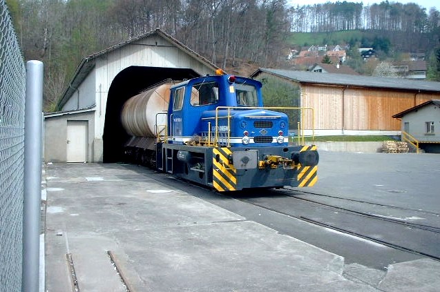
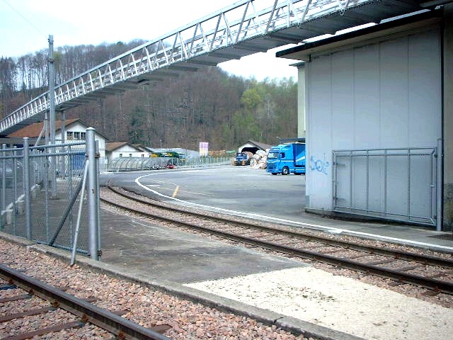
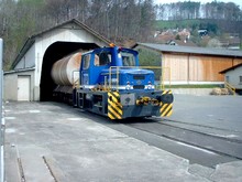
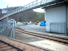
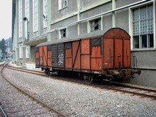
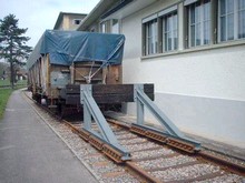
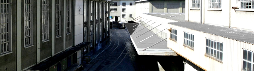
special freight stock. Here are five views taken in
April 2002 depicting the internal rail service at the
cardboard factory in Deisswil (Switzerland), illustrating
typical aspects of this type of traffic (since shut down
along with the factory).
|
| |
|
| |
| Motive power is
provided by a small company-owned shunter (which was
acquired new in this specific case, but which could well
be a second-hand shunter bought from a larger private or
state-owned rail company). The track is both covered (in
places where road traffic needs to have access) and
ballasted, with fencing present prominently - after all
this is private property. The factory buildings represent
a mix of older and more modern structures, and different
types of freight rolling stock to meet the requirements
of the rail customer - in this case tank cars (for liquid
chemicals), covered freight cars (for solid material
which needs some protection) and open freight cars,
covered with tarpaulins in some cases, for material which
will not suffer from exposure.
|
| |
| The
advantage of an operational concept governing traffic
flow is added realism and an extra challenge when
switching. The setback is just as evident: the example
above is definitely not suited for a layout which boasts
a collection of 20+ coal hoppers - unless the plant
actually runs on coal. |
| |
| |
Traffic
flow - what goes where and why
|
|
|
| |
| Once
an operational concept for a switching layout is drawn up
and established, the only thing needed to finally do some
interesting and challenging switching is to generate the
traffic flow. Over the years, a number of systems doing
precisely this (generally referred to as "car
forwarding systems") have originated with American
prototype modellers. Although rarely used for other
prototype modelling, all of these systems work equally
well for any kind of standard railway system. |
| |
| The specified
car switch list generates
instructions for freight cars on a layout, taking into
account their type and potential delivery locations. The
basic concept of most car card systems goes back to Doug
Smith's description in the December 1961 issue of Model
Railroader. The
most popular specified car switch list system is Don
McFall's Card and Waybill
system which works as follows:
|
| |
 |
|
Step
1
The waybill is slipped into the transparent
pocket of the card, and the boxcar in question is
switched to the Consolidated Tooling Company for
unloadingStep
2
Reversing the waybill, the boxcar has now been
unloaded and loaded again; it is taken to its new
destination, the Atlantic Warehouses
Step 3
According to the directions on the waybill, it is
removed once the boxcar has reached its
destination, revealing that after unloading it is
to return empty to the Westside Yard
|
|
| |
| Obviously, these physical cards
can be - and to an increasing extent are - substituted by
virtual cards or screen output on a computer system or
handheld device which will also take care of the chance
car selection and load distribution. |
| |
| Whereas the card and
waybill system centers on identifying individual freight
stock and linking these with destination orders, the Scenario
List System
focusses on customers, i.e. locations and industries,
where freight may be picked up and/or delivered. |
| |
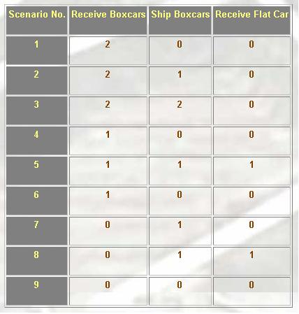
| Each
industry on a layout is analysed in terms of
possible scenarios. The Consolidated Tooling
Company, for example, is assumed to receive and
ship products mainly in boxcars, but occasionally
also to receive goods transported on a flat car.
The possible scenarios here are: Customer
receives 0-2 boxcars, ships 0-2 boxcars, receives
0-1 flat car. A selection is made from all
possible combinations in order to produce the
scenarios given as example here. For
every operating session, one of these scenarios
is selected for the "Consolidated Tooling
Co". In order to acknowledge that according
to the traffic flow concept worked out for this
customer some of these scenarios are supposed to
be more frequent than others, the scenario list
is broken down to scenario cards (one card giving
one scenario) in varying numbers. As a result,
scenarios 2 and 3 would appear on 5 scenario
cards each, whereas all scenarios involving the
delivery of a flat car would only have one.
Shuffling these cards, the chances of having a
flat car delivered would thus be smaller. Once
the "move" is made, the card goes to
the back of the deck of scenario cards, making
sure that flat cars won't appear too frequently
at the "Consolidated Tooling Co."
This
system works well for small layouts and is fairly
realistic in its approach: rail customers usually
don't care at all whether the boxcar used to ship
their goods is brown, green, yellow or pink as
long as they turn up on time and in sufficient
numbers.
|
|
 |
|
| |
| Due to its
flexibility regarding choice of rolling stock to be used,
this system may not produce challenges in the sense of
asking you, by chance, to switch the most awkwardly
placed boxcar to the tightest spot on the layout - but
there's always the possibility of creating additional
rules if things seem to get too easy. |
| |
| |
Getting
real - car spots and the "modern
minimalist" approach
|
|
|
| |
| The majority of shunting and
switching layouts are rooted in what could loosely be
called the steam/diesel transition era - for two reasons.
First, as seen above, the concept began to be popularized
in the 1950s and 1960s, and secondly both motive power
and rolling stock from that era are considerably shorter
than their more modern counterparts (e.g. 40' boxcars
rather than 50' or even 60' boxcars) and therefore allow
for smaller layouts. |
| |
 |
|
Combining this era (when even
less-than-carload traffic by rail was still
common) with the necessary compression of railway
modelling very often results in single-car
industries on shunting layouts. For modellers who
want to replicate current railway operations,
however, this conceptual formula simply doesn't
match up with the real world. For several years now a
number of modellers - who almost exclusively
model North American railroads - have come up
with ideas and answers on how to adapt the
shunting layout formula in order to make it both
workable and realistic for modelling the modern
railway scene.
Amongst these, Lance Mindheim is probably the
best known, as he combines stunning modelling
with a fully fledged concept of how to design,
build and operate a realistic (modern) switching
layout which he has highlighted in four books
published between 2009 and 2011 (How to
Design a Small Switching Layout, 8
Realistic Track Plans for Small Switching Layouts,
How to Build a Switching Layout, and How
to Operate a Modern Era Switching Layout).
His various Florida industrial park and spur
layouts have almost become a model railroading sub-genre,
inspiring many subsequent Sunshine State
switching layouts; Mindheim also runs a blog on
model railroad design in conjunction with his
commercial layout planning service.
|
|
| |
| Mindheim takes his cue from the
essence of what characterizes contemporary railroad
companies: their striving for efficiency in the face of
strong competition from road transport, which - if we
take the example of Norfolk Southern's Creed - translates
as "we will provide quality service, always
trying to reduce costs to offer competitive prices".
He then transposes this to modern railroad operations and
stipulates two main principles: |
| |
| 1 |
|
Keep the trackwork simple
A switch is a costly device: it requires handling
in the process of switching (costing the railroad
time while it's doing its job) and needs
maintenance (which actually costs the railroad
money). Therefore, contemporary track layouts
have done away with all unnecessary switches,
resulting in some cases in single track
industrial spurs of substantial length - which in
model form could mean a switching layout with
just one or two sidings.
A runaround track requires at least two switches,
and having the locomotive run around its train
consumes time and fuel, so the trackage in a
modern industrial park will most likely only have
switches pointing in one direction so that the
switcher can push and pull cars without the need
to run around its train. Therefore, you should
aim to not put a runaround where the prototype
doesn't need or have one. |
|
| |
| 2 |
|
Designate
multiple car spots for one switching
destination
The "one car customer" is, in
all but a few exceptions, a thing of the
past, and has been replaced either by
large rail customer complexes or by
switching destinations (such as a
warehouse) which in effect serve multiple
customers.
Therefore, you should have structures on
your layout with at least two designated
places where freight cars can be set out,
most probably serving more than one
customer. |
|
|
| |
| Putting these two principles to
work on a modern switching layout does take it very close
to being prototypically correct. The result from a
"traditional perspective", however, is a very
simple track layout which looks rather bare and most
probably also lacks one of the railroad modeller's
favourite devices, the runaround track, as well as other
"complications" such as switchback sidings
(which is why I refer to it as the "modern
minimalist" approach). |
| |
| However, unlike the traditional
steam/diesel transition era layout, the
operational "spice" on such a modern
switching layout is not generated by the
trackplan, but by the way the spurs and
industries situated along them are switched - by
using so-called car spots. As railroads
merged and lost their local foothold, names or
random numbers given to tracks serving customers
became incomprehensible to a centralized dispatch
structure.
Parallel to
the introduction of computer systems in the late
1960s, US railroads drew up industry schematic
maps for their road crews. They list industry
information such as where to spot loaded or empty
cars for unloading/loading for a specific
customer, the track capacities, and other
pertinent information, all in a consistent
format.
Different US railroads use(d)
differing terminology for this car spot
designation system; the acronym SPINS is an
abbreviation for Southern Pacific Industry
Numbering System - it originated on the SP
but was also used by e.g. BN. CLIC (Car
Location Identity Codes) was a Santa Fe term
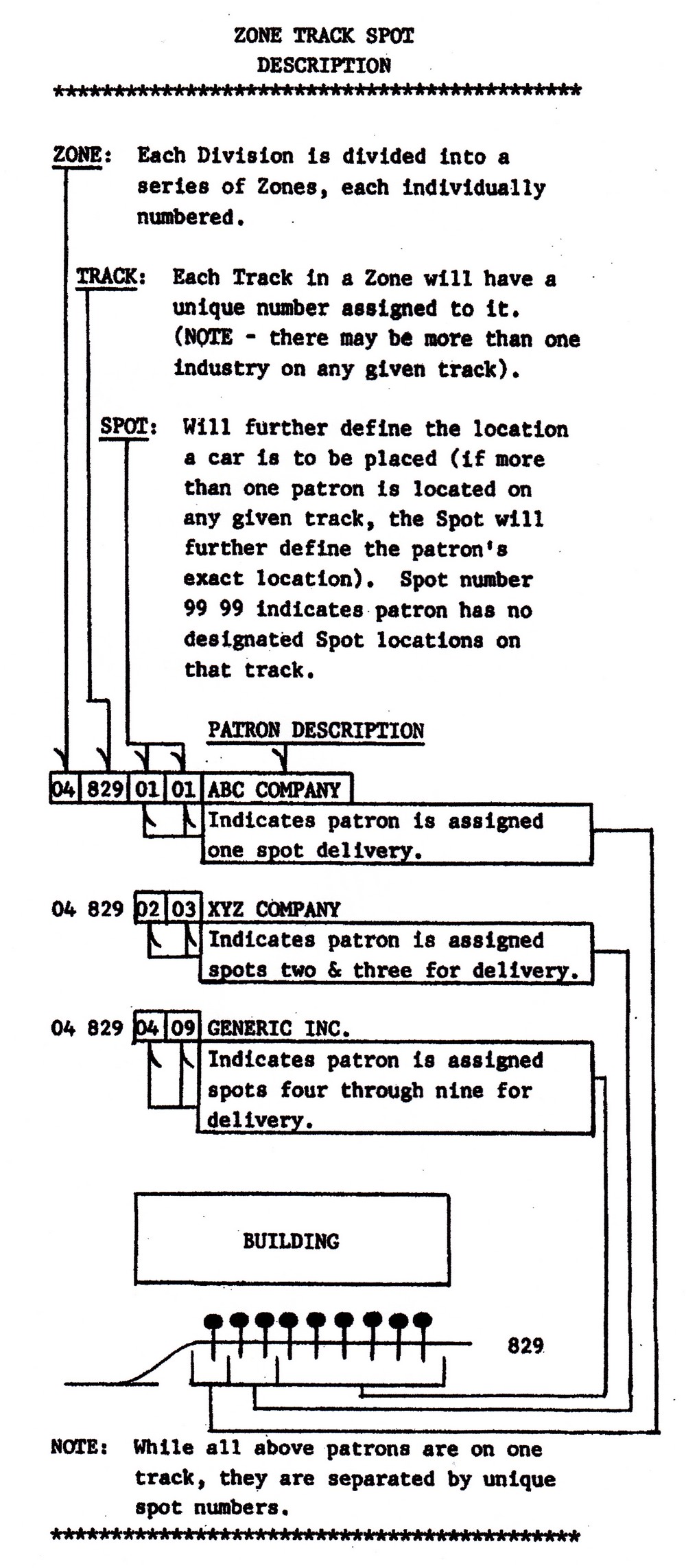
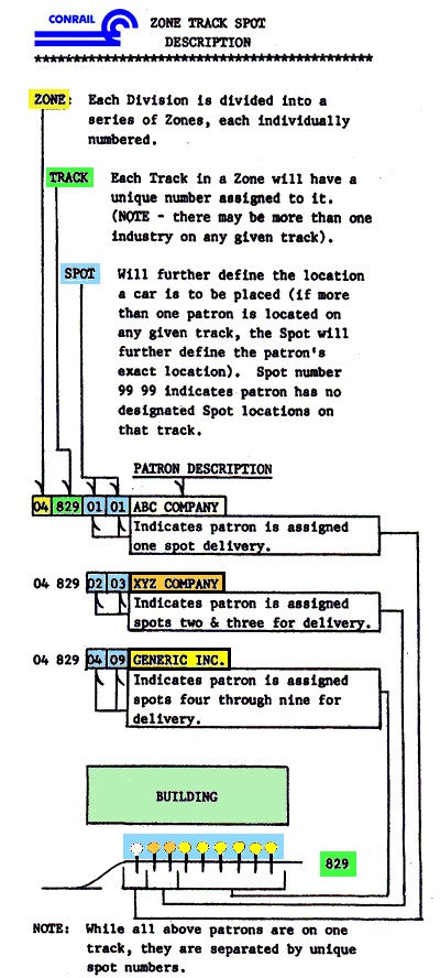
for the same thing, as was ZTS (Zone, Track,
Spot) on Conrail.
The example
shown here comes from the 1987 Conrail ZTS for
its New England Division - and really explains it
all. If a freight car is to be set out at
04-829-07, then the ZTS map will tell any crew
that its destination is car spot 07 on track 829
in Zone 04, and that the customer in question is
the Generic Inc.
It is also easy to see how
requiring freight cars to be placed in specific
spots can add not only additional realism to a
modern era switching layout but also beef up the
challenge of operating it considerably. All of a
sudden, that single industrial spur doesn't seem
that bleak anymore.
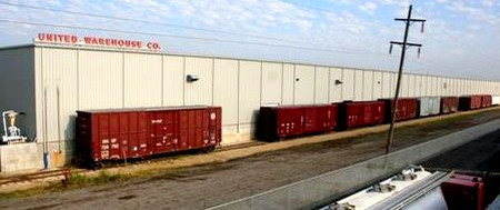
The United Warehouse in Wichita
illustrates what this looks like in real life,
but even a drastically shortened building can
provide operating interest on a switching layout
using car spots if it either serves several
customers or a single customer requires specific
goods to be delivered to specific locations on
his spur.
|
|
 |
|
| |
| Switching on a "minimalist
modern" layout will mostly consist of pushing and
pulling cars in and out of sidings until the required
order is arrived at - and as such is in fact very similar
to switching an Inglenook
Sidings puzzle. Just like the latter, cars could be
assigned spots by e.g. the random throw of a dice; in his
books, Lance Mindheim suggests setting up the switching
order yourself but making the most of the switcher's
moves by imitating certain prototype procedures and
remembering to take it slow as switching in 1:1 scale is
a time consuming job. |
| |
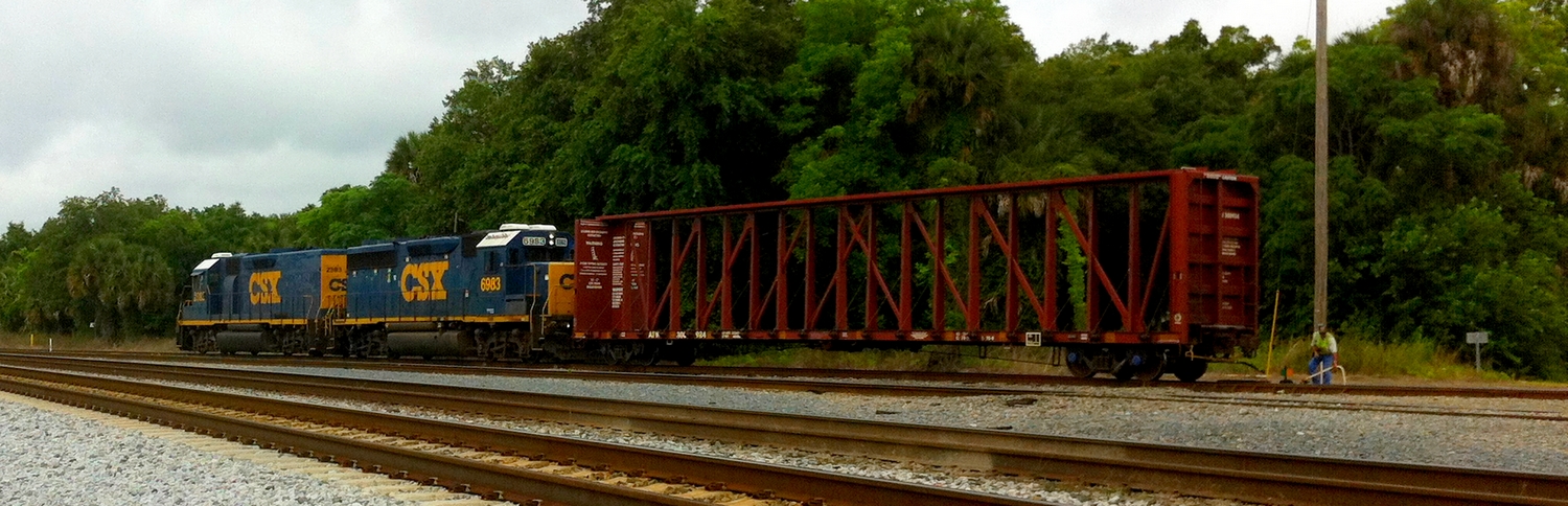
The conductor is
throwing a switch in Wildwood FL yard in May 2014 as CSX
"road slug" GP39-2 #2383 and GP40-2 #6983 are
busy pushing and pulling cars as described above -
although in this case they are not serving car spots but
rather "blocking" a consist, i.e. making up a
northbound train.
|
| |
| Again not necessarily small in
size, a modern era switching layout can offer a lot more
operating potential than its simple trackplan might
suggest if a car spotting system is used. Naturally, many
prototype locations still have more complex trackwork in
evidence today (a fact Mindheim and others are more than
willing to admit), but it is becoming the exception. And
ultimately the simple track layout has the same advantage
for the modeller that it has for the real railroad
company: fewer switches and less track means spending
less money on infrastructure and less time on
maintenance. |
| |
| Probably
the main attraction of a "modern
minimalist" switching layout is that it
allows the use of contemporary rolling stock with
single car payloads - which has become a rarity
in the age of the "block train"
(carrying a long string of freight cars loaded
with the same cargo, e.g. containers or coal) but
which used to be the railway's daily bread. Using
"car spotting" thus works just as well
for a 1950's or 1960's layout and is not
restricted to any geographical area at all. The new goods shed in Peterborough
embodied British Railway's perception of
modernised freight working by rail; goods vans
could be unloaded either into the goods shed
(where a conveyor belt helped in moving the goods
to their correct storage space) or outwards onto
road vehicules which distributed the goods
elsewhere.
|
|
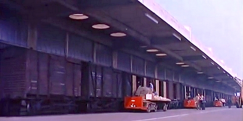
A long row
of 12t goods vans standing at the newly
modernized Peterborough goods shed in 1960
|
|
| |
| It
was a 1960's version of a transload facility, which
certainly required the goods vans to be set out in the
correct order so that they ended up being
"spotted" where they were needed. |
| |
| |
From a
shunting layout to a shunting puzzle
|
|
|
| |
| All of the systems of
operating a shunting layout discussed above have one
purpose: to generate interest by means of a consistent
traffic flow. Although they may come up with some awkward
shunting moves, they are not designed to introduce such
complications deliberately. Most of the time, things will
flow easily. A shunting puzzle, however, is a
shunting layout which deliberately introduces
complications which need to be solved in order to get the
shunting done. Usually, these complications are generated
by a set of restrictions or rules. For example, sidings
can be short and thus require the operator to think ahead
of his moves unless he wants everything clogged up, or
rules may require a certain specific order into which
freight stock must be shunted.
The
example layout used above to illustrate a possible
operational concept based on a paper factory, by the way,
uses the "Timesaver"
trackplan - the classic US switching puzzle. The classic
British shunting puzzle, the "Inglenook Sidings", features a significantly less
complex trackwork, whilst a "tuning fork" switching puzzle reduces it all to
the max by only having one point and two sidings.
|
| |
More about Shunting
Puzzles
|
| |

|
| |
|
| |
| BIBLIOGRAPHY Freezer Cyril J.
(1961) "Another layout for the holidays", in Railway
Modeller (August 1961 issue)
Hayden Bob (ed.)
(1981) Track planning ideas from Model Railroader,
Kalmbach Publishing
|
| |
Text,
photos and illustrations not labelled otherwise are © Adrian Wymann
Page created: 26/JAN/2001
Last revised: 14/SEPT/2024
|
| |